Lightning Fast Orders!
Call Now To Place a Quick Order
Call an Expert-Fast Response
Call 1-866-595-9616
KMParts.com is "THE" source for industrial automation control components
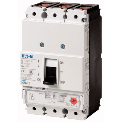
NZMB1-S8-CNA
Circuit Breaker
NZMB1-S8-CNA
Circuit Breaker
NZMB1-S8-CNA
Circuit Breaker
- Short-Circuit Protection
- Thermomagnetic Release
- Conforms to UL/CSA & IEC Regulations
- 4 Compact Sizes
- 3 Poles
Description:
NZMB1-S8-CNA circuit-breakers cover all application cases with just four compact sizes and are suitable for use in the worldwide market. Modular function groups always make mounting flexible. With magnetic short-circuit release in connection with overload relay. With short-circuit release lacking overload trip. Notes: Switches conform to UL/CSA as well as IEC regulations. The rating plate contains IEC switching performance values.
NZMB1-S8-CNA
Technical Specifications
Main Specifications
| Description | NZMB1-S8-CNA Base Unit |
|---|---|
| Product range | Circuit-breaker |
| Protective function | Short-circuit protection |
| Standard/Approval | UL |
| Installation type | Fixed |
| Release system | Thermomagnetic release |
| Description | Motor protection in conjunction with contactor and overload relay With short-circuit release Without overload release Ir |
| Number of poles | 3 pole |
| Standard equipment | Box terminal |
| Rated current = rated uninterrupted current [In = Iu] | 8 A |
| Description | NZMB1-S8-CNA Base Unit | |
|---|---|---|
| Standards | UL/CSA | |
| Protection against direct contact | Finger and back of hand proof to VDE 0106 Part 100 | |
| Climatic proofing | Damp heat, constant, to IEC 60068-2-78 Damp heat, cyclic, to IEC 60068-2-30 | |
| Ambient temperature Ambient temperature, storage | - 40 - + 70 °C | |
| Ambient temperature Operation | -25 - +70 °C | |
| Mechanical shock resistance (10 ms half-sinusoidal shock) according to IEC 60068-2-27 | 20 (half-sinusoidal shock 20 ms) g | |
| Safe isolation to EN 61140 Between auxiliary contacts and main contacts | 500 V AC | |
| Safe isolation to EN 61140 between the auxiliary contacts | 300 V AC | |
| Mounting position |

Vertical and 90° in all directions With XFI earth-fault release: - NZM1, N1, NZM2, N2: vertical and 90° in all directions with plug-in unit - NZM1, N1, NZM2, N2: vertical, 90° right/left with withdrawable unit: - NZM3, N3: vertical, 90° right/left - NZM4, N4: vertical with remote operator: - NZM2, N(S)2, NZM3, N(S)3, NZM4, N(S)4: vertical and 90° in all directions |
|
| Direction of incoming supply | as required | |
| Degree of protection Device | In the operating controls area: IP20 (basic degree of protection) | |
| Degree of protection Enclosures | With insulating surround: IP40 With door coupling rotary handle: IP66 | |
| Degree of protection Terminations | Tunnel terminal: IP10 Phase isolator and strip terminal: IP00 | |
| Other technical data (sheet catalogue) | Weight Temperature dependency, Derating Effective power loss | |
| Description | NZMB1-S8-CNA Base Unit |
|---|---|
| Short-circuit releases [Irm
] Non-delayed [Ii = In x …] | 6 - 11 |
| Description | NZMB1-S8-CNA Base Unit |
|---|---|
| Rated surge voltage invariability [Uimp
] Main contacts | 6000 V |
| Rated surge voltage invariability [Uimp
] Auxiliary contacts | 6000 V |
| Rated operational voltage [Ue] | 440 V AC |
| Overvoltage category/pollution degree | III/3 |
| Rated insulation voltage [Ui ] | 690 V |
| Description | NZMB1-S8-CNA Base Unit |
|---|---|
| Lifespan, mechanical(of which max. 50 % trip by shunt/undervoltage release) [Operations] | 20000 |
| Lifespan, electrical AC--3 415 V 50/60 Hz [Operations] | 7500 |
| Lifespan, electrical Max. operating frequency | 120 Ops/h |
| Total break time at short-circuit | < 10 ms |
| Description | NZMB1-S8-CNA Base Unit |
|---|---|
| Standard equipment | Box terminal |
| Round copper conductor Box terminal Solid | 1 x (12 … 6) mm2 |
| Round copper conductor Box terminal Stranded | 1 x (4 … 2/0) mm2 |
| Round copper conductor Tunnel terminal Solid | 1 x 6 mm2 |
| Round copper conductor Tunnel terminal Stranded Stranded | 1 x (4 … 3/0) mm2 |
| Round copper conductor Bolt terminal and rear-side connection Direct on the switch Solid | 1 x (12 … 6) 2 x (9 … 6) mm2 |
| Round copper conductor Bolt terminal and rear-side connection Direct on the switch Stranded | 1 x (4 … 2/0) mm2 |
| Al conductors, Cu cable Tunnel terminal Solid | 1 x 16 mm2 |
| Cu strip (number of segments x width x segment thickness) Box terminal [min.] | 2 x 9 x 0.8 mm |
| Cu strip (number of segments x width x segment thickness) Box terminal [max.] | 9 x 9 x 0.8 mm |
| Copper busbar (width x thickness) [mm] Bolt terminal and rear-side connection Screw connection | M6 |
| Copper busbar (width x thickness) [mm] Bolt terminal and rear-side connection Direct on the switch [min.] | 12 x 5 mm |
| Copper busbar (width x thickness) [mm] Bolt terminal and rear-side connection Direct on the switch [max.] | 16 x 5 mm |
| Control cables | 1 x (18 … 14) 2 x (18 … 16) mm2 |
| Description | NZMB1-S8-CNA Base Unit |
|---|---|
| Rated operational current for specified heat dissipation [In] | 8 A |
| Equipment heat dissipation, current-dependent [Pvid] | 1.76 W |
| Operating ambient temperature min. | -25 °C |
| Operating ambient temperature max. | +70 °C |
| Description | NZMB1-S8-CNA Base Unit |
|---|---|
| 10.2 Strength of materials and parts 10.2.2 Corrosion resistance | Meets the product standard's requirements. |
| 10.2 Strength of materials and parts 10.2.3.1 Verification of thermal stability of enclosures | Meets the product standard's requirements. |
| 10.2 Strength of materials and parts 10.2.3.2 Verification of resistance of insulating materials to normal heat | Meets the product standard's requirements. |
| 10.2 Strength of materials and parts 10.2.3.3 Verification of resistance of insulating materials to abnormal heat and fire due to internal electric effects | Meets the product standard's requirements. |
| 10.2 Strength of materials and parts 10.2.4 Resistance to ultra-violet (UV) radiation | Meets the product standard's requirements. |
| 10.2 Strength of materials and parts 10.2.5 Lifting | Does not apply, since the entire switchgear needs to be evaluated. |
| 10.2 Strength of materials and parts 10.2.6 Mechanical impact | Does not apply, since the entire switchgear needs to be evaluated. |
| 10.2 Strength of materials and parts 10.2.7 Inscriptions | Meets the product standard's requirements. |
| 10.3 Degree of protection of ASSEMBLIES | Does not apply, since the entire switchgear needs to be evaluated. |
| 10.4 Clearances and creepage distances | Meets the product standard's requirements. |
| 10.5 Protection against electric shock | Does not apply, since the entire switchgear needs to be evaluated. |
| 10.6 Incorporation of switching devices and components | Does not apply, since the entire switchgear needs to be evaluated. |
| 10.7 Internal electrical circuits and connections | Is the panel builder's responsibility. |
| 10.8 Connections for external conductors | Is the panel builder's responsibility. |
| 10.9 Insulation properties 10.9.2 Power-frequency electric strength | Is the panel builder's responsibility. |
| 10.9 Insulation properties 10.9.3 Impulse withstand voltage | Is the panel builder's responsibility. |
| 10.9 Insulation properties 10.9.4 Testing of enclosures made of insulating material | Is the panel builder's responsibility. |
| 10.10 Temperature rise | The panel builder is responsible for the temperature rise calculation. Eaton will provide heat dissipation data for the devices. |
| 10.11 Short-circuit rating | Is the panel builder's responsibility. The specifications for the switchgear must be observed. |
| 10.12 Electromagnetic compatibility | Is the panel builder's responsibility. The specifications for the switchgear must be observed. |
| 10.13 Mechanical function | The device meets the requirements, provided the information in the instruction leaflet (IL) is observed. |
| Description | NZMB1-S8-CNA Base Unit |
|---|---|
| Low-voltage industrial components (EG000017) / Motor protection circuit-breaker (EC000074) | |
| Electric engineering, automation, process control engineering / Low-voltage switch technology / Circuit breaker (LV < 1 kV) / Motor protection circuit-breaker (ecl@ss10.0.1-27-37-04-01 [AGZ529016]) | |
| Overload release current setting | 0 - 0 A |
| Adjustment range undelayed short-circuit release | 6 - 11 A |
| With thermal protection | No |
| Phase failure sensitive | No |
| Switch off technique | Magnetic |
| Rated operating voltage | 440 - 440 V |
| Rated permanent current Iu | 8 A |
| Rated operation power at AC-3, 230 V | 1.5 kW |
| Rated operation power at AC-3, 400 V | 3 kW |
| Type of electrical connection of main circuit | Other |
| Type of control element | Rocker lever |
| Device construction | Built-in device fixed built-in technique |
| With integrated auxiliary switch | No |
| With integrated under voltage release | No |
| Number of poles | 3 |
| Rated short-circuit breaking capacity lcu at 400 V, AC | 25 kA |
| Degree of protection (IP) | IP20 |
| Height | 165.5 mm |
| Width | 90 mm |
| Depth | 88 mm |
| Description | NZMB1-S8-CNA Base Unit |
|---|---|
| Product Standards | UL 489 |
| UL File No. | E31593 |
| UL Category Control No. | DKPU2 |
| North America Certification | UL recognized |
| Conditions of Acceptability | Only used in motor circuits in conjunction with suitable contactor and overload relay. SCCR value applies for complete combination starter only, consisting of instantaneous trip circuit breaker, contactor and overload relay. |
| Specially designed for North America | Yes |
| Suitable for | Branch circuits, feeder circuits |
| Current Limiting Circuit-Breaker | No |
| Max. Voltage Rating | 480Y/277 V |
| Degree of Protection | UL/CSA Type: - |
| Description | NZMB1-S8-CNA Base Unit |
|---|---|
| Characteristic curve |

|
| Short-circuit protection only! | |
| Characteristic curve |

|
| Characteristic curve |

|
| Description | NZMB1-S8-CNA Base Unit |
|---|---|

|
|
| ① Blow out area, minimum clearance to adjacent parts | |

|
Copyright © 2022 KMParts.com


- Phone: +1-866-595-9616
- Fax: +1-941-473-0987
- Email: sales@kmparts.com
- Address: 1580 Market Cir #1
- Port Charlotte, FL 33953
- Hours: M-F 7:30a.m. - 5:30p.m. EDT