Menu

Moeller ETR4-69-A
is now
EATON XTTR6A100H69B

SAME EXACT PART- ONLY PART # CHANGE
Multi-Function Electronic Timing Relay
Operating Voltage 24-240 Volts AC or DC
Contact Rating EC Rated
operational
current l at
AC-15
220V, 230V, 240V
Actuating
Voltage
UL/CSA Pilot
Duty Rating
Time Range
Eaton/Moeller ETR4-69-A Multi-Function Electronic Timing Relay

ETR4-69-A

3 24-240V DC
24-240, 50/60 Hz
B 300 0.05 - 100 h

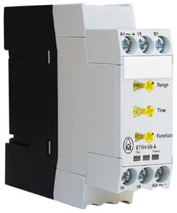
Selectable Range switch on timer sets the maximum time that the potentiometer shown on the right utilizes. ETR4-69-A Timing Relay Range Setting

Combined with the maximum range selector switch the below Potentiometer on the timer adjusts to your exact requirement
ETR4-69-A Timing Relay Timing Setting

Clock Graphic

Full Scale Range Select
100 h 100 h on the Range Selector Knob =

(0.5-10=0.5 to
100 Hours)
on the time adjust
 
30 h 30 h on the Range Selector Knob =

(1.5-30=1.5 to
30 Hours)
on the time adjust
300 s 300 s on the Range Selector Knob =

(1.5-30=15 to
300 Seconds)
on the time adjust
80 s 100 s on the Range Selector Knob =

(0.5-10=0.5 to
100 Seconds)
on the time adjust
1.8 s 3 s on the Range Selector Knob =

(1.5-30=.15 to
3 Seconds)
on the time adjust
0.2 s 1 s on the Range Selector Knob =

(0.5-10=0.5 to
100 Seconds)
on the time adjust


Clock Graphic

Time within range
100h
0.5-10 =
0.5 to 100 Hours
on the time adjust


3 h


1.5 - 30 = 1.5 to
30 Hours
on the time adjust


120 s


1.5 - 30 = 15 to
300 Seconds
on the time adjust


80 s


0.5 - 10 = 0.5 to
100 Seconds
on the time adjust
 
1.8 s


1.5-30=.15 to
3 Seconds
on the time adjust


0.2 s
0.5 - 10= 0.5 to
100 Seconds
on the time adjust


 Download button graphic

Multi-function relay
ETR4
01/08 AWA2527-1485
[307 KB] [07.03.2002]PDF Icon


Accuracy of resistance value: g 10% (linear)

ETR4-69-A Dimensions

ETR4-69-A Timing RelayDimensions Diagram

Inch to MM Conversion

Convert to MM

MM to Inch Conversion

Convert to Inches

ETR4-69-A Timing Relay Function Setting

1 Instantaneous Contact, 1 Timed Contact A2/X1 not jumped together

WITHOUT B1
ETR4-69-A Timing Relay Circuit Diagram minus B1

WITH B1
ETR4-69-A Timing Relay Circuit Diagram with B1

With A1 and B1 either connected together or at the same potential through an external contact.

11 On-Delayed
21 With Fleeting Make Contact
42 Flashing
81 Pulse Generating
12 Off-Delayed
16 On and Off Delayed
22 With Fleeting Break Contact
82 Pulse Shaping


 ETR4-11-A  ETR4-51-A ETR4-69-A ETR4-70-A ETR Index
 ETR4-11-W  ETR4-51-W ETR4-69-W ETR4-70-W

Let our expert sales staff guide you through finding the right products to fit your needs. CALL 866-595-9616.