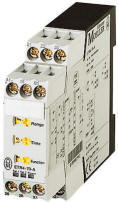
Selectable Range switch on timer
sets the maximum time that the potentiometer shown
on the right utilizes.

|
Combined with the maximum range
selector switch the below Potentiometer on the timer
adjusts to your exact requirement
 |

|
Full Scale Range Select |
| 100
h |
100 h on the Range Selector Knob =
(0.5-10=0.5 to
100 Hours)
on
the time adjust
|
| 30 h |
30 h on
the Range Selector Knob =
(1.5-30=1.5 to
30 Hours)
on the
time adjust |
| 300 s |
300 s on
the Range Selector Knob =
(1.5-30=15 to
300 Seconds)
on
the time adjust |
| 80
s |
100 s on the Range Selector Knob =
(0.5-10=0.5 to
100 Seconds)
on
the time adjust |
| 1.8 s |
3 s on
the Range Selector Knob =
(1.5-30=.15 to
3 Seconds)
on the
time adjust |
| 0.2
s |
1 s on the Range Selector Knob =
(0.5-10=0.5 to
100 Seconds)
on
the time adjust |
|
|
Time within range |
| 100h |
0.5-10 =
0.5 to 100 Hours
on the
time adjust
|
3 h
nnbsp; |
1.5 - 30
= 1.5 to
30 Hours
on the time
adjust |
120 s
|
1.5 - 30
= 15 to
300 Seconds
on the time
adjust
|
80 s
|
0.5 - 10 = 0.5 to
100 Seconds
on
the time adjust
|
1.8 s
|
1.5-30=.15 to
3 Seconds
on the
time adjust
|
| 0.2
s |
0.5 - 10= 0.5 to
100 Seconds
on the time adjust
|
|
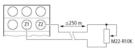
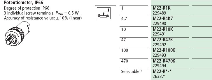
M22-R10K
Remote mounted Potentiometer for applications that
need operator access) |
|
|
Degree of protection IP66
3 individual screw terminals, Pmax = 0.5 W
|
 |

|
Mounts in standard 22mm or 7/8"
pushbutton hole.
|
Other
resistances available in the M22 potentiometer line
but only use the M22-R10K with the timers. |
 |
 |
Multi-function relay
ETR4
01/08 AWA2527-1485
[307
KB] [07.03.2002] |
|
Accuracy of resistance value: g 10% (linear)
ETR4-70-A Dimensions
|
 |
1
Instantaneous Contact, 1 Timed Contact A2/X1 not
jumped together |
|
With A1 and B1 either
connected together or at the same potential through
an external contact. |
|
|
|
|
|
2 Timed
Contacts, A2/X1 open not jumped |
|
With A1 and B1 either connected
together or at the same potential through an
external contact.
|
|
|
|
|