Eaton Series-C Motor Circuit Protectors
Motor Circuit Protectors (MCP)
Product Description
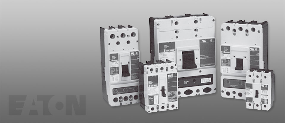
Designated as Eaton’s Types GMCP and HMCP, the instantaneous-only motor circuit protector (MCP) is available in ratings from 3A to 1200A for motor starter sizes 0 through 8.
An innovative design of internal components allows higher MCP-starter combination interrupting ratings. The MCP is marked to permit proper electrical application within the assigned equipment ratings.
Standards and Certifications
The MCP is designed to comply with the applicable requirements of Underwriters Laboratories Standard UL 489, Canadian Standards Association Standard C22.2 No. 5.1, and International Electrotechnical Commission RecommendationsIEC 157-1.
The MCP is a recognized component (UL File E7819) and complies with the applicable requirements of Underwriters Laboratories Standard UL 489. It is also designed to comply with the applicable requirements of Canadian Standards Association Standard C22.2 No. 5.1, International Electrotechnical Commission Recommendations IEC 157-1, and nameplates bear the CE marking.
Note: Interrupting ratings are dependent on starter it is used with.
G-Frame — 480 Vac Maximum, 600Y/347 Vac
| NEMA Starter Size |
Continuous Amperes |
Cam Setting | Motor Full Load Current Amperes (FLA)(1) |
MCP Trip Setting |
MCP Part Number |
| 0 | 3 | A | 1.1–1.2 | 15 | GMCP003A0C |
| B | 1.3–1.5 | 18 | |||
| C | 1.6–1.7 | 21 | |||
| D | 1.8–1.9 | 24 | |||
| E | 2.0–2.2 | 27 | |||
| F | 2.3–2.5 | 30 | |||
| 0 | 7 | A | 2.6–3.1 | 35 | GMCP007C0C |
| B | 3.2–3.6 | 42 | |||
| C | 3.7–3.9 | 49 | |||
| D | 4.3–4.7 | 56 | |||
| E | 4.8–5.2 | 63 | |||
| F | 5.3–5.7 | 70 | |||
| 0 | 15 | A | 5.7–6.8 | 150 | GMCP015H1C |
| B | 6.9–7.9 | 180 | |||
| C | 8.0–9.1 | 210 | |||
| D | 9.2–10.3 | 240 | |||
| E | 10.4–11.4 | 270 | |||
| F | 11.5–12.6 | 300 | |||
| 1 | 30 | A | 11.5–13.7 | 250 | GMCP030H1C |
| B | 13.8–16.0 | 300 | |||
| C | 16.1–18.3 | 350 | |||
| D | 18.4–20.6 | 400 | |||
| E | 20.7–22.9 | 450 | |||
| F | 23.0–25.2 | 500 | |||
| 2 | 50 | A | 19.3–22.9 | 250 | GMCP050K2C |
| B | 23.0–26.8 | 300 | |||
| C | 26.9–30.6 | 350 | |||
| D | 30.7–34.5 | 400 | |||
| E | 34.6–38.3 | 450 | |||
| F | 38.4–42.1 | 500 | |||
| 3 | 60 | A | 23.1–27.5 | 300 | GMCP060J2C |
| B | 27.7–32.2 | 360 | |||
| C | 32.3–36.7 | 420 | |||
| D | 36.9–41.4 | 480 | |||
| E | 41.5–46.0 | 540 | |||
| F | 46.2–50.5 | 600 | |||
| 3 | 63 | A | 24.2–32.1 | 320 | GMCP063M2C |
| B | 29.1–34.8 | 380 | |||
| D | 38.8–46.4 | 500 | |||
| E | 43.6–48.9 | 570 | |||
| F | 48.5–53.7 | 630 |
NOTES:
(1) Motor FLA ranges are typical. The corresponding trip setting is at 13 x the minimum FLA value shown. Where a 13 x setting is required for an intermediate FLA value, alternate Cam settings and/or MCP ratings should be used.
All GMCP 3–63A come with line and load steel body terminals for Cu only wire. Refer to Page V4-T2-116 under Optional Terminal Types.
UL recognized and CSA approved.
Accessories
Modifications for GMCP
Internal accessories must be factory installed.
Internal Accessories(1)
| Type Accessory |
Electrical Ratings | Amperes | Contact Arrangement |
Factory Suffix |
Style Number |
|
| Volts | Frequency | |||||
| Shunt trip(2) | 120 | 50/60 Hz | 1.1 | — | S5 | 1373D62G18 |
| Shunt trip(2) | 240 | 50/60 Hz | 2.1 | — | S6 | 1373D62G19 |
| Auxiliary switch(3) | 240 | 50/60 Hz | 6.0 | 1A/1B | A3 | 1288C74G03 |
| Auxiliary switch(3) | 240 | 50/60 Hz | 6.0 | 2A/2B | A6 | 1288C73G03 |
| Alarm switch(3) | 240 | 50/60 Hz | 6.0 | Make/Break | B3 | 1288C75G03 |
| Auxiliary switch/alarm switch combination(3) |
240 | 50/60 Hz | 6.0 | 1A/1B Make/Break | B13 | 1288C76G09 |
External Mounted Accessories
| Description | Number Units in Package |
Style Number |
| Lock dog (non-padlockable) | 1 | 1294C01H01 |
| Mounting hardware | 1 | 624B375G23 |
| DIN rail adapter(4) | 10 | 1225C79G02 |
Handle Mechanisms for Series C Frames
Kits Only (Kit Includes Shaft, Mechanism and Handle)—GMCP-Frame
| Description | Rating Type NEMA |
IP | GMCP-Frame Part Number |
| S01 blue handle, 12-inch shaft |
1/3R/12 | 54 | GMHMVD12B / 68C6039G05 |
| 4/4X | 65 | GMHMVD12BX / 68C6039G07 | |
| S01 red handle, 12-inch shaft |
1/3R/12 | 54 | GMHMVD12R / 68C6039G06 |
| 4/4X | 65 | GMHMVD12RX / 68C6039G08 |
Direct (Close-Coupled) Handle Mechanisms — G Direct(5)
| Frame | Black Handle | Yellow Handle | ||
| With Shroud | Without Shroud | With Shroud | Without Shroud | |
| GMCP | HRGMC1S | HRGMC10 | HRGMC3S | HRGMC30 |
NOTES:
(1) Only one accessory may be installed in GMCP.
(2) LH only.
(3) RH only.
(4) For use with standard 35 mm DIN rail such as, 35 x 7.5 or 15 mm per DIN EN50022.
(5) Suitable for use on two- or three-pole G-Frame.
No UVR available on GMCP.
F-Frame — 600 Vac Maximum, 250 Vdc Maximum
| NEMA Starter Size |
Cont. Amps |
Cam Setting |
Motor Full Load Current Amperes (FLA)(1) |
MCP Trip Setting(2) |
MCP |
| 0 | 3 | A | 0.69–0.91 | 9 | HMCP003A0C |
| B | 0.92–1.0 | 12 | |||
| C | 1.1–1.2 | 15 | |||
| D | 1.3–1.5 | 18 | |||
| E | 1.6–1.7 | 21 | |||
| F | 1.8–1.9 | 24 | |||
| G | 2.0–2.2 | 27 | |||
| H | 2.3–2.5 | 30 | |||
| 0 | 7 | A | 1.5–2.0 | 21 | HMCP007C0C |
| B | 2.1–2.5 | 28 | |||
| C | 2.6–3.1 | 35 | |||
| D | 3.2–3.6 | 42 | |||
| E | 3.7–3.9 | 49 | |||
| F | 4.3–4.7 | 56 | |||
| G | 4.8–5.2 | 63 | |||
| H | 5.3–5.7 | 70 | |||
| 0 | 15 | A | 3.4–4.5 | 45 | HMCP015E0C |
| B | 4.6–5.6 | 60 | |||
| C | 5.7–6.8 | 75 | |||
| D | 6.9–7.9 | 90 | |||
| E | 8.0–9.1 | 105 | |||
| F | 9.2–10.3 | 120 | |||
| G | 10.4–11.4 | 135 | |||
| H | 11.5 –12.6 | 150 | |||
| 1 | 30 | A | 6.9–9.1 | 90 | HMCP030H1C |
| B | 9.2–11.4 | 120 | |||
| C | 11.5–13.7 | 150 | |||
| D | 13.8–16.0 | 180 | |||
| E | 16.1–18.3 | 210 | |||
| F | 18.4–20.6 | 240 | |||
| G | 20.7–22.9 | 270 | |||
| H | 23.0–25.2 | 300 | |||
| 2 | 50 | A | 11.5–15.2 | 150 | HMCP050K2C |
| B | 15.3–19.1 | 200 | |||
| C | 19.2–22.9 | 250 | |||
| D | 23.0–26.8 | 300 | |||
| E | 26.9–30.6 | 350 | |||
| F | 30.7–4.5 | 400 | |||
| G | 34.6–38.3 | 450 | |||
| H | 38.4–42.1 | 500 | |||
| 2 | 70 | A | 16.1–21.4 | 210 | HMCP070M2C |
| B | 21.5 –26.8 | 280 | |||
| C | 26.9 –32.2 | 350 | |||
| D | 32.3–37.5 | 420 | |||
| E | 37.6–42.9 | 490 | |||
| F | 43.0–48.3 | 560 | |||
| G | 48.4–53.7 | 630 | |||
| H | 53.8–59.1 | 700 | |||
| 3 | 100 | A | 23.0–30.6 | 300 | HMCP100R3C |
| B | 30.7–38.3 | 400 | |||
| C | 38.4–46.0 | 500 | |||
| D | 46.1–53.7 | 600 | |||
| E | 53.8 –61.4 | 700 | |||
| F | 61.5 –69.1 | 800 | |||
| G | 69.2–76.8 | 900 | |||
| H | 76.9–84.5 | 1000 | |||
| 4 | 150 | A | 34.6–46.0 | 450 | HMCP150T4C |
| B | 46.1–57.5 | 600 | |||
| C | 57.6–69.1 | 750 | |||
| D | 69.2–80.6 | 900 | |||
| E | 80.7–92.2 | 1050 | |||
| F | 92.3–103.7 | 1200 | |||
| G | 103.8–115.2 | 1350 | |||
| H | 115.3–126.7 | 1500 | |||
| 4 | 150 | A | 57.0 –75.0 | 750 | HMCP150U4C |
| B | 76.0–95.0 | 1000 | |||
| C | 96.0–114.0 | 1250 | |||
| D | 115.0–130.7 | 1500 | |||
| E | (3) | 1750 | |||
| F | (3) | 2000 | |||
| G | (3) | 2250 | |||
| H | (3) | 2500 |
NOTES:
(1) Motor FLA ranges are typical. The corresponding trip setting is at 13 x the minimum FLA value shown. Where a 13 x setting is required for an intermediate FLA value, alternate Cam settings and/or MCP ratings should be used.
(2) For DC applications, actual trip levels are approximately 40% higher than values shown.
(3) Settings above 130 amperes are for special applications. NEC Article 430.110(a) requires the ampere rating of the disconnecting means to be not less than 115% of the motor full load ampere rating.
HMCP 3–100A come with line and load steel body terminals, 3T100FB. HMCP 150A come with line and load steel body terminals, 3T150FB.
Special Low Magnetic Protection Application MCP — 600 Vac Maximum, 250 Vdc Maximum
| Cont. Amps |
Cam Setting |
MCP Trip Setting 1 |
MCP |
| 25 | A | 40 | HMCP025D0C |
| B | 43 | ||
| D | 49 | ||
| E | 52 | ||
| F | 55 | ||
| G | 58 | ||
| H | 60 | ||
| 50 | A | 80 | HMCP050G2C |
| B | 87 | ||
| C | 93 | ||
| D | 98 | ||
| E | 103 | ||
| F | 109 | ||
| G | 115 | ||
| H | 120 | ||
| 70 | A | 115 | HMCP070J2C |
| B | 122 | ||
| C | 130 | ||
| D | 139 | ||
| E | 145 | ||
| F | 153 | ||
| G | 160 | ||
| H | 170 | ||
| 100 | A | 160 | HMCP100L3C |
| B | 174 | ||
| C | 185 | ||
| D | 196 | ||
| E | 207 | ||
| F | 218 | ||
| G | 229 | ||
| H | 240 |
NOTES:
(1) For DC applications, actual trip levels are approximately 40% higher than values shown.
HMCP 25–100A come with line and load steel body terminals, 3T100FB.
MCPs for Application with Motor Starters Equipped with Electronic Overload Relays
600 Vac Maximum, 250 Vdc Maximum
| NEMA Starter Size |
Cont. Amps |
Cam Setting |
Motor Full Load Current Amperes (FLA)(1) |
MCP Trip Setting(2) |
MCP |
| 0 | 3 | A | 0.69–0.91 | 9 | HMCPS003A0C |
| B | 0.92–1.0 | 12 | |||
| C | 1.1–1.2 | 15 | |||
| D | 1.3–1.5 | 18 | |||
| E | 1.6–1.7 | 21 | |||
| F | 1.8–1.9 | 24 | |||
| G | 2.0–2.2 | 27 | |||
| H | 2.3–2.5 | 39 | |||
| 0 | 7 | A | 1.5–2.0 | 21 | HMCPS007C0C |
| B | 2.1–2.5 | 28 | |||
| C | 2.6–3.1 | 35 | |||
| D | 3.2–3.6 | 42 | |||
| E | 3.7–3.9 | 49 | |||
| F | 4.3–4.7 | 56 | |||
| G | 4.8–5.2 | 63 | |||
| H | 5.3–5.7 | 70 | |||
| 0 | 15 | A | 3.4–4.5 | 45 | HMCPS015E0C |
| B | 4.6–5.6 | 60 | |||
| C | 5.7–6.8 | 75 | |||
| D | 6.9–7.9 | 90 | |||
| E | 8.0–9.1 | 105 | |||
| F | 9.2–10.3 | 120 | |||
| G | 10.4–11.4 | 135 | |||
| H | 11.5–12.6 | 150 | |||
| 1 | 30 | A | 6.9–9.1 | 90 | HMCPS030H1C |
| B | 9.2–11.4 | 120 | |||
| C | 11.5–13.7 | 150 | |||
| D | 13.8–16.0 | 180 | |||
| E | 16.1–18.3 | 210 | |||
| F | 18.4–20.6 | 240 | |||
| G | 20.7–22.9 | 270 | |||
| H | 23.0–25.2 | 300 | |||
| 2 | 50 | A | 11.5–15.2 | 150 | HMCPS050K2C |
| B | 15.3–19.1 | 200 | |||
| C | 19.2–22.9 | 250 | |||
| D | 23.0–26.8 | 300 | |||
| E | 26.9–30.6 | 350 | |||
| F | 30.7–34.5 | 400 | |||
| G | 34.6–38.3 | 450 | |||
| H | 38.4–42.1 | 500 | |||
| 3 | 100 | A | 23.0–30.6 | 300 | HMCPS100R3C |
| B | 30.7–38.3 | 400 | |||
| C | 38.4–46.0 | 500 | |||
| D | 46.1–53.7 | 600 | |||
| E | 53.8–61.4 | 700 | |||
| F | 61.5–69.1 | 800 | |||
| G | 69.2–76.8 | 900 | |||
| H | 76.9–84.5 | 1000 | |||
| 4 | 150 | A | 34.6–46.0 | 450 | HMCPS150T4C |
| B | 46.1–57.5 | 600 | |||
| C | 57.6–69.1 | 750 | |||
| D | 69.2–80.6 | 900 | |||
| E | 80.7–92.2 | 1050 | |||
| F | 92.3–103.7 | 1200 | |||
| G | 103.8–115.2 | 1350 | |||
| H | 115.3–126.7 | 1500 | |||
| 4 | 150 | A | 57.0–75.0 | 750 | HMCPS150U4C |
| B | 76.0–95.0 | 1000 | |||
| C | 96.0–114.0 | 1250 | |||
| D | 115.0–130.7 | 1500 | |||
| E | (3) | 1750 | |||
| F | (3) | 2000 | |||
| G | (3) | 2250 | |||
| H | (3) | 2500 |
NOTES:
(1) Motor FLA ranges are typical. The corresponding trip setting is at 13 x the minimum FLA value shown. Where a 13 x setting is required for an intermediate FLA value, alternate cam settings and/or MCP ratings should be used.
(2) For DC applications, actual trip levels are approximately 40% higher than values shown.
(3) Settings above 130A are for special applications. NEC Article 430.110(a) requires the ampere rating of the disconnecting means to be not less than 115% of the motor full load ampere rating.
HMCP 25–100A come with line and load steel body terminals, 3T100FB.
HMCPS 3–100A come with line and load steel body terminals, 3T100FB. HMCPS 150A come with line and load steel body terminals, 3T150FB.
J-Frame — 600 Vac Maximum, 250 Vdc Maximum
| NEMA Starter Size |
Cont. Amps |
Cam Setting |
Motor Full Load Current Amperes (FLA)(1) |
MCP Trip Setting(2) |
MCP(3) |
| 4 | 250 | A | 27.0–30.7 | 350 | HMCP250A5C |
| B | 30.8–33.8 | 400 | |||
| C | 33.9–36.9 | 440 | |||
| 5 | 250 | D | 37.0–40.3 | 480 | |
| E | 40.4–43.8 | 525 | |||
| F | 43.9–46.9 | 570 | |||
| G | 47.0–50.7 | 610 | |||
| H | 47.0–50.7 | 660 | |||
| I | 47.0–50.7 | 700 | |||
| 5 | 250 | A | 34.7–38.8 | 450 | HMCP250C5C |
| B | 38.9–43.4 | 505 | |||
| C | 43.5–47.6 | 565 | |||
| D | 47.7–52.2 | 620 | |||
| E | 52.3–56.5 | 680 | |||
| F | 56.6–60.7 | 735 | |||
| G | 60.8–64.9 | 790 | |||
| H | 65.0–69.2 | 845 | |||
| I | 69.3–73.5 | 900 | |||
| 5 | 250 | A | 38.5–43.4 | 500 | HMCP250D5C |
| B | 43.5–48.0 | 565 | |||
| C | 48.1–53.0 | 625 | |||
| D | 53.1–57.6 | 690 | |||
| E | 57.7–62.3 | 750 | |||
| F | 62.4–67.3 | 810 | |||
| G | 67.4–71.9 | 875 | |||
| H | 72.0–76.9 | 935 | |||
| I | 77.0–81.6 | 1000 | |||
| 5 | 250 | A | 48.1–53.8 | 625 | HMCP250F5C |
| B | 53.9–59.9 | 700 | |||
| C | 60.0–66.1 | 780 | |||
| D | 66.2–72.3 | 860 | |||
| E | 72.4–78.4 | 940 | |||
| F | 78.5–83.8 | 1020 | |||
| G | 83.9–89.9 | 1090 | |||
| H | 90.0–96.1 | 1170 | |||
| I | 96.2–102.0 | 1250 | |||
| 5 | 250 | A | 57.7–64.6 | 750 | HMCP250G5C |
| B | 64.7–71.9 | 840 | |||
| C | 72.0–79.2 | 935 | |||
| D | 79.3–86.5 | 1030 | |||
| E | 86.6–93.8 | 1125 | |||
| F | 93.9–101.1 | 1220 | |||
| G | 101.2–108.4 | 1315 | |||
| H | 108.5–115.3 | 1410 | |||
| I | 115.4–122.4 | 1500 | |||
| 5 | 250 | A | 67.4–75.3 | 875 | HMCP250J5C |
| B | 75.4–83.8 | 980 | |||
| C | 83.9–92.3 | 1090 | |||
| D | 92.4–100.7 | 1200 | |||
| E | 100.8–109.2 | 1310 | |||
| F | 109.3–117.6 | 1420 | |||
| G | 117.7–126.1 | 1530 | |||
| H | 126.2–134.6 | 1640 | |||
| I | 134.7–142.8 | 1750 | |||
| 5 | 250 | A | 77.0–86.6 | 1000 | HMCP250K5C |
| B | 86.6–96.1 | 1125 | |||
| C | 96.2–105.7 | 1250 | |||
| D | 105.8–115.3 | 1375 | |||
| E | 115.4–124.9 | 1500 | |||
| F | 125.0–134.6 | 1625 | |||
| G | 134.7–144.2 | 1750 | |||
| H | 144.3–153.8 | 1875 | |||
| I | 153.9–163.3 | 2000 | |||
| 5 | 250 | A | 86.6–97.3 | 1125 | HMCP250L5C |
| B | 97.4–108.4 | 1265 | |||
| C | 108.5–118.8 | 1410 | |||
| D | 118.9–129.9 | 1545 | |||
| E | 130.0–140.7 | 1690 | |||
| F | 140.8–151.5 | 1830 | |||
| G | 151.6–162.3 | 1970 | |||
| H | 162.4–173.0 | 2110 | |||
| I | 173.1–183.6 | 2250 | |||
| 5 | 250 | A | 96.2–108.0 | 1250 | HMCP250W5C |
| B | 108.1–119.9 | 1405 | |||
| C | 120.0–132.3 | 1560 | |||
| D | 132.4–144.2 | 1720 | |||
| E | 144.3–156.1 | 1875 | |||
| F | 156.2–168.0 | 2030 | |||
| G | 168.1–179.9 | 2185 | |||
| H | 180.0–192.3 | 2340 | |||
| I | 192.4–204.0 | 2500 |
NOTES:
(1) Motor FLA ranges are typical. The corresponding trip setting is at 13 times the minimum FLA value shown. Where a 13 times setting is required for an intermediate FLA value, alternate cam settings and/or MCP ratings should be used.
(2) For DC applications, actual trip levels are approximately 40% higher than values shown.
(3) Three-pole catalog numbers shown. Two-pole catalog numbers begin with HM2P in placeof HMCP.
All HMCP and HM2P 250A come with line and load steel body terminals, T250KB. (With suffix “C,” without “C” comes with TA250KB.)
K-Frame — 600 Vac Maximum, 250 Vdc Maximum
| NEMA Starter Size |
Cont. Amps |
Cam Setting |
Motor Full Load Current Amperes (FLA)(1) |
MCP Trip Setting(2) |
MCP(3) |
| 4 | 400 | A | 27.0–30.7 | 350 | HMCP400A5C |
| B | 30.8–33.8 | 400 | |||
| C | 33.9–36.9 | 440 | |||
| 5 | 400 | D | 37.0–40.3 | 480 | HMCP400A5C |
| E | 40.4–43.8 | 525 | |||
| F | 43.9–46.9 | 570 | |||
| G | 47.0–50.7 | 610 | |||
| H | 50.8–53.8 | 660 | |||
| I | 53.9–57.2 | 700 | |||
| 5 | 400 | A | 38.5–43.4 | 500 | HMCP400D5C |
| B | 43.5–48.0 | 565 | |||
| C | 48.1–53.0 | 626 | |||
| D | 53.1–57.6 | 690 | |||
| E | 57.7–62.3 | 750 | |||
| F | 62.4–67.3 | 810 | |||
| G | 67.4–71.9 | 875 | |||
| H | 72.0–76.9 | 935 | |||
| I | 77.0–81.6 | 1000 | |||
| 5 | 400 | A | 48.1–53.8 | 625 | HMCP400F5C |
| B | 53.9–59.9 | 700 | |||
| C | 60.0–66.1 | 780 | |||
| D | 66.2–72.3 | 860 | |||
| E | 72.4–78.4 | 940 | |||
| F | 78.5–83.8 | 1020 | |||
| G | 83.9–89.9 | 1090 | |||
| H | 90.0–96.1 | 1170 | |||
| I | 96.2–102.0 | 1250 | |||
| 5 | 400 | A | 57.7–64.6 | 750 | HMCP400G5C |
| B | 64.7–71.9 | 840 | |||
| C | 72.0–79.2 | 935 | |||
| D | 79.3–86.5 | 1030 | |||
| E | 86.6–93.8 | 1125 | |||
| F | 93.9–101.1 | 1220 | |||
| G | 101.2–108.4 | 1315 | |||
| H | 108.5–115.3 | 1410 | |||
| I | 115.4–122.4 | 1500 | |||
| 5 | 400 | A | 67.4–75.3 | 875 | HMCP400J5C |
| B | 75.4–83.8 | 980 | |||
| C | 83.9–92.3 | 1090 | |||
| D | 92.4–100.7 | 1200 | |||
| E | 100.8–109.2 | 1310 | |||
| F | 109.3–117.6 | 1420 | |||
| G | 117.7–126.1 | 1530 | |||
| H | 126.2–134.6 | 1640 | |||
| I | 134.7–142.8 | 1750 | |||
| 5 | 400 | A | 77.0–86.5 | 1000 | HMCP400K5C |
| B | 86.6–96.1 | 1125 | |||
| C | 96.2–105.7 | 1250 | |||
| D | 105.8–115.3 | 1375 | |||
| E | 115.4–124.9 | 1500 | |||
| F | 125.0–134.6 | 1625 | |||
| G | 134.7–144.2 | 1750 | |||
| H | 144.3–153.8 | 1875 | |||
| I | 153.9–163.3 | 2000 | |||
| 5 | 400 | A | 86.6–97.3 | 1125 | HMCP400L5C |
| B | 97.4–108.4 | 1265 | |||
| C | 108.5–118.8 | 1410 | |||
| D | 118.9–129.9 | 1545 | |||
| E | 130.0–140.7 | 1690 | |||
| F | 140.8–151.5 | 1830 | |||
| G | 151.6–162.3 | 1970 | |||
| H | 162.4–173.0 | 2110 | |||
| I | 173.1–183.6 | 2250 | |||
| 5 | 400 | A | 96.2–108.0 | 1250 | HMCP400W5C |
| B | 108.1–119.9 | 1405 | |||
| C | 120.0–132.3 | 1560 | |||
| D | 132.4–144.2 | 1720 | |||
| E | 144.3–156.1 | 1875 | |||
| F | 156.2–168.0 | 2030 | |||
| G | 168.1–179.9 | 2185 | |||
| H | 180.0–192.3 | 2340 | |||
| I | 192.4–204.0 | 2500 | |||
| 5 | 400 | A | 115.4–129.9 | 1500 | HMCP400N5C |
| B | 130.0–144.2 | 1690 | |||
| C | 144.3–158.4 | 1875 | |||
| D | 158.5–173.0 | 2060 | |||
| E | 173.1–187.6 | 2250 | |||
| F | 187.7–201.9 | 2440 | |||
| G | 202.0–216.1 | 2625 | |||
| H | 216.2–230.7 | 2810 | |||
| I | 230.8–244.9 | 3000 | |||
| 5 | 400 | A | 134.7–151.5 | 1750 | HMCP400R5C |
| B | 151.6–168.4 | 1970 | |||
| C | 168.5–185.3 | 2190 | |||
| D | 185.4–201.9 | 2410 | |||
| E | 202.0–218.8 | 2625 | |||
| F | 218.9–235.7 | 2845 | |||
| G | 235.8–252.6 | 3065 | |||
| H | 252.7–269.2 | 3285 | |||
| I | 269.3–285.7 | 3500 | |||
| 5 | 400 | A | 153.9–173.0 | 2000 | HMCP400X5C |
| B | 173.1–192.3 | 2250 | |||
| C | 192.4–211.5 | 2500 | |||
| D | 211.6–230.7 | 2750 | |||
| E | 230.8–249.9 | 3000 | |||
| F | 250.0–269.2 | 3250 | |||
| G | 269.3–288.4 | 3500 | |||
| H | 288.5–307.6 | 3750 | |||
| I | 307.7–326.9 | 4000 | |||
| 4 | 400 | A | 173.1–194.5 | 2250 | HMCP400Y5C |
| B | 194.6–216.1 | 2530 | |||
| C | 216.2–237.6 | 2810 | |||
| D | 237.7–259.5 | 3090 | |||
| E | 259.6–281.1 | 3375 | |||
| F | 281.2–302.6 | 3655 | |||
| G | 302.7–324.1 | 3935 | |||
| H | 324.2–346.1 | 4215 | |||
| I | 346.2–368.1 | 4500 |
NOTES:
(1) Motor FLA ranges are typical. The corresponding trip setting is at 13 x the minimum FLA value shown. Where a 13 x setting is required for an intermediate FLA value, alternate cam settings and/or MCP ratings should be used.
(2) For DC applications, actual trip levels are approximately 40% higher than values shown.
(3) Three-pole catalog numbers shown. Two-pole catalog numbers begin with HM2P in place of HMCP.
All HMCP and HM2P 400A come with aluminum body terminals, 3TA400K. Catalog numbers with suffix “C” as shown above come with copper body terminals 3T400K.
L-Frame — 600 Vac Maximum(4)
| NEMA Starter Size |
Cont. Amps |
Cam Setting |
Motor Full Load Current Amperes (FLA)(1) |
MCP Trip Setting |
MCP |
| 6 | 600 | A | 138.5–184.5 | 1800 | HMCP600L6W |
| B | 184.6–230.7 | 2400 | |||
| C | 230.8–276.8 | 3000 | |||
| D | 276.9–323.0 | 3600 | |||
| E | 323.1–369.1 | 4200 | |||
| F | 369.2–415.3 | 4800 | |||
| G | 415.4–461.4 | 5400 | |||
| H | 461.5–507.7 | 6000 | |||
| 6 | 600 | A | 38.5–46.1 | 500 | HMCP600X6W |
| B | 46.2–61.4 | 600 | |||
| C | 61.5–76.8 | 800 | |||
| D | 76.9–96.1 | 1000 | |||
| E | 96.2–115.3 | 1250 | |||
| F | 115.4–153.7 | 1500 | |||
| G | 153.8–192.2 | 2000 | |||
| H | 192.3–230.7 | 2500 | |||
| 6 | 600 | A | 76.9–96.1 | 1000 | HMCP600Y6W |
| B | 96.2–115.3 | 1250 | |||
| C | 115.4–153.7 | 1500 | |||
| D | 153.8–192.2 | 2000 | |||
| E | 192.3–230.7 | 2500 | |||
| F | 230.8–269.1307.7–346.1 | 3000 | |||
| G | 269.2–307.6 | 3500 | |||
| H | 4000 |
NOTES:
(1) Motor FLA ranges are typical. The corresponding trip setting is at 13 x the minimum FLA value shown. Where a 13 x setting is required for an intermediate FLA value, alternate cam settings and/or MCP ratings should be used.
(2) For DC applications, actual trip levels are approximately 40% higher than values shown.
(3) Three-pole part numbers shown. Two-pole catalog numbers begin with HM2P in place of HMCP.
(4) Equipped with electronic trip device.
All HMCP and HM2P 400A come with aluminum body terminals, 3TA400K. Catalog numbers with suffix “C” as shown above come with copper body terminals 3T400K.
All HMCP 600A come without terminals.
N-Frame — 600 Vac Maximum(1)
| NEMA Starter Size |
Cont. Amps |
Cam Setting |
Motor Full Load Current Amperes (FLA)(2) |
MCP Trip Setting |
MCP |
| 7 | 800 | A | 123.1–184.5 | 1600 | HMCP800X7W |
| B | 184.6–246.1 | 2400 | |||
| C | 246.2–307.6 | 3200 | |||
| D | 307.7–369.1 | 4000 | |||
| E | 369.2–430.7 | 4800 | |||
| F | 430.8–492.2 | 5600 | |||
| G | 492.3–553.7 | 6400 | |||
| 8 | 1200 | A | 184.6–276.8 | 2400 | HMCP12Y8W |
| B | 276.9–369.1 | 3600 | |||
| C | 369.2–461.4 | 4800 | |||
| D | 461.5–553.7 | 6000 | |||
| E | 553.8–646.1 | 7200 | |||
| F | 646.2–738.4 | 8400 | |||
| G | 738.5–830.7 | 9600 |
NOTES:
(1) Equipped with electronic trip device.
(2) Motor FLA ranges are typical. The corresponding trip setting is at 13X the minimum FLA value shown. Where a 13X setting is required for an intermediate FLA value, alternate cam settings and/or MCP ratings should be used.