Eaton A200 Series - NEMA Contactors, Starters, Relays & Shoe Breakes
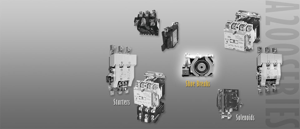
Shoe Brakes—AC and DC, 511 Series
Size S-4 Brake and Wheel
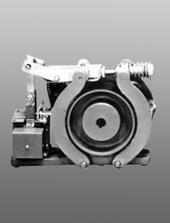
Product DescriptionType S Brakes from Eaton’s Electrical Sector are electrically released and spring applied providing “fail-safe” operation. The retarding torque developed is directly proportional to the spring pressure. Application Description
Product Selection
|
FeaturesThe brake wheel is of relatively large size in relation to the torque developed by the brake. This permits use of a larger brake shoe lining and lower shoe pressures. Low shoe pressure, equally distributed over a large lining area, results in even wear of the friction surfaces and even braking torque. The oversize wheel type construction also permits use of a smaller operating solenoid that requires less current for a given torque rating. DC BrakesStandard DC brakes are equipped with shunt coils. The magnet coil circuit on DC brakes consists of two separate windings and a protective switch. MountingType S brakes are designed and recommended for use and mounting only in the horizontal position. Side or vertical mountings are not recommended because the solenoid loading is altered, resulting in accelerated wear and premature coil failure. |
Type S Brakes—Floor Mounting
| Torque—lb-ft | Brake Size |
AC Base Part Number (2)(3) |
For Type S4, S5-1/2, S7, S10 | DC Base Part Number (2)(3) |
Coil Voltage |
Coil Suffix (2) |
||
| Continuous | Intermittent (1) | Coil Volts and Hertz |
Coil Suffix (2) |
|||||
| 3 | 3 | S-4 | 511H1194 | 120V 60 Hz 208V 60 Hz 240V 60 Hz 480V 60 Hz 600V 60 Hz 110V 50 Hz 220V 50 Hz 380V 50 Hz 440V 50 Hz 550V 50 Hz |
-39 -45 -40 -41 -58 -5 -6 -7 -8 -9 |
511H955 | 120 Vdc 240 Vdc |
-97 -98 |
| 10 | 10 | S-4 | 511H1193 | 511H956 | ||||
| - | 15 | S-4 | 511H1192 | 511H957 | ||||
| 25 | 25 | S-5.5 | 511H992 | 511H994 | ||||
| - | 35 | S-5.5 | 511H993 | 511H995 | ||||
| 50 | 50 | S-7 | 511H970 | 511H975 | ||||
| - | 70 | S-7 | 511H971 | 511H976 | ||||
| 85 | 85 | S-7 | 511H1195 | 511H1197 | ||||
| - | 100 | S-7 | 511H1196 | 511H1198 | ||||
Notes:
(1) Intermittent duty indicates that the coil can be placed across the line continuously for one hour maximum without excessive heating. It is equivalent to 1/2 time ON and 1/2 time OFF.
(2) Add suffix number for coil voltage to base catalog number.
(3) Does not include wheel.
Brake Selection
| The method most
generally used to determine required braking torque is to calculate the full load motor torque by the following formula: |
||
| T | = | 5252 x hp |
| rpm | ||
| T | = | Full load motor torque in lb-ft |
| hp | = | Motor horsepower |
| rpm | = | Speed of shaft on which brake wheel is mounted |
| The torque rating of the brake selected
should be at least equal to the full load motor torque for the duty considered. |
||
| Wheel Size in Inches |
Min. Bore in Inches (mm) |
Max. Bore in Inches (mm) |
Pilot Bore in Inches (mm) |
WK2 | Straight Bore (1) Base (3) Part Number |
Tapered Bore (1) Base (3) Part Number |
| 4.0 | 0.50 (12.7) | 1.38 (35.1) | 0.50 (12.7) | 0.06 | 511H1150 | 511H1151 |
| 5.5 | 0.75 (19.1) | 2.00 (50.8) | 0.75 (19.1) | 0.26 | 511H1160 | 511H1161 |
| 7.0 | 1.00 (25.4) | 2.25 (57.2) | 0.75 (19.1) | 0.77 | 511H1170 | 511H1171 |
Brake Wheel Suffix Numbers
| Bore Size Suffix Number—Add to Base Catalog Number | |||||
| Bore (4) in Inches (mm) |
Keyway in Inches |
Suffix Number |
Bore (4) in Inches (mm) |
Keyway in Inches (mm) |
Suffix Number |
| Standard Bore Sizes | |||||
| Pilot bore | None | -1 | 1.625 (41.28) | 3/38 x 3/16 | -9 |
| 0.625 (15.88) | 3/16 x 3/32 | -2 | 1.875 (47.63) | 1/2 x 1/4 | -10 |
| 0.750 (19.05) | 3/16 x 3/32 | -3 | 2.125 (53.98) | 1/2 x 1/4 | -11 |
| 0.875 (22.23) | 3/16 x 3/32 | -4 | 2.375 (60.33) | 5/8 x 5/16 | -12 |
| 1.000 (25.40) | 1/4 x 1/8 | -5 | 2.500 (63.50) | 5/8 x 5/16 | -63 |
| 1.125 (28.58) | 1/4 x 1/8 | -6 | 2.625 (66.68) | 5/8 x 5/16 | -13 |
| 1.250 (31.75) | 1/4 x 1/8 | -7 | 2.750 (69.85) | 5/8 x 5/16 | -18 |
| 1.375 (34.93) | 5/16 x 5/32 | -8 | 2.875 (73.03) | 3/4 x 3/8 | -14 |
| Non-Standard Bore Sizes | |||||
| 0.500 (12.70) | 1/8 x 1/16 | -50 | 1.687 (42.85) | 3/8 x 3/16 | -58 |
| 0.750 (19.05) | 1/4 x 1/8 | -51 | 1.750 (44.45) | 3/8 x 3/16 | -59 |
| 0.875 (22.23) | 1/4 x 1/8 | -52 | 1.937 (49.20) | 1/2 x 1/4 | -60 |
| 1.000 (25.40) | 5/16 x 5/32 | -53 | 2.000 (50.80) | 1/2 x 1/4 | -61 |
| 1.187 (30.15) | 1/4 x 1/8 | -54 | 2.250 (57.15) | 1/2 x 1/4 | -62 |
| 1.375 (34.93) | 3/8 x 3/16 | -55 | - | - | - |
| 1.437 (36.50) | 3/8 x 3/16 | -56 | - | - | - |
| 1.500 (38.10) | 3/8 x 3/16 | -57 | - | - | - |
Notes:
(1) Bore tolerance: +0.000–0.001 in.
(2) Taper is at rate of 1.25 in per ft on diameter. In bore size selection, use diameter of tapered shaft. Bore tolerance: +0.000–0.005 in.
(3) Add suffix number for bore size to base catalog number.
(4) Bore size selected must be between minimum and maximum dimensions listed in brake wheel selection table.