Menu

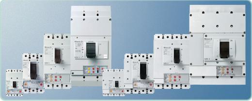
Moeller NZM Overview
System, Generator and Motor Protection

NZM1 NZM2 NZM3 NZM4 NZM7 NZM10
25-160 Amp 32-250 Amp 125-630 Amp 315-1600 Amp 25-150 Amp 150-600 Amp

Motor Protection, Generator Protection, System Protection

System Protection

System Protection
NZM protects systems

NZM circuit-breakers protect entire systems as well as cables and wiring on all levels, from the main distribution board right up to the loads.

As the incoming circuit-breaker, the NZM will of course also provide secondary side overload protection for the transformer.

A variant with modified short-circuit releases also enables a power network with time selectivity.

Motor Protection

Motor Protection
NZM protects motors

NZM circuit-breakers protect motors and cables against overloads and short-circuits.

The short-circuit release of the NZM can be set to 12 to 14 times the rated motor current to ensure that starting current peaks are not shut down by the protective device.

NZM circuit breakers provide reliable and phase failure sensitive protection for motors from 15 A to 1400 A.

Generator Protection

Generator Protection
NZM protects generators
Even when the generators have difficulty generating two to six times the continuous current, it does not present a problem for the NZM.

It can master shutdown of even the smallest short-circuit currents within a few milliseconds.

A setting which ignores short-circuit currents for up to 1 s is possible for special tasks.

Protection with Fault Currents NZM protects with fault
currents

The mains and auxiliary voltage independent residual current circuit-breaker trips as soon as the set rated fault currents are exceeded.

The module is pulse current sensitive and also discriminative. The I∆N = 30 ma in this function module also ensures personnel safety.


Trip Electronics featuring microprocessors for Motor protection

Trip electronics featuring microprocessors enhance the operating continuity

The microprocessor controlled digital electronics determine RMS values for the load current to be monitored. In contrast to analog electronics, any harmonics which may be in the power grid will be correctly evaluated and do
not cause premature and unexpected trips.

This prevents a standstill. Special components simulate a thermal memory even when the switch trips during a current less period due to a load overload. Thus, safe protection of the connected equipment is guaranteed – even when the device is switched back on after a brief cooling off phase. All electronics have been routinely tested and pre-aged in an oven.

This corresponds to a real operating time of about six months. Thermocouples guarantee a safety-oriented trip of the circuit-breaker in the improbable case that an inadmissible over temperature is due to the electronic components.

NZM1, nzm3, NZM3, NZM4 Selectivity Table
NZM Selectivity table
NZM circuit-breakers achieve selectivity during a short-circuit even without additional electronic short-time delayed devices.

For example, the 1000 A circuit breaker in combination with a 250 A outgoing circuit-breaker is fully selective up to a maximum existing short-circuit current of 100 000 A.

Even two high energy incoming supplies of e.g. two parallel 2 000 kVA distribution transformers are cost-effective and are simple to engineer with high levels of supply reliability.


All messages in detail – the Data Management Interface


It does not matter if the causes for a trip or a warning message with unbalance are required, or if all phase currents are to be displayed directly on-site and corrective actions are to be implemented with a critical load state.

The Data Management Interface (DMI) always signals exact details. The relay outputs of the DMI signal up to 6 different messages. All trip causes are available as group signals and Ii, Ir, Isd, I2t, and Idn detail signals.

The trip cause, phase state, switch setting as well as date and time can be accessed via the 4-line display. Representation of the actual phase currents can be in absolute or relative (% Ir) terms.

Warnings with regard to the load status are issued at 70 %, 100 % and 120 % Ir. Thus, the DMI is perfect for direct display on-site or for the integration in higher-level energy management concepts.


Let our expert sales staff guide you through finding the right products to fit your needs. CALL 866-595-9616.