Eaton/Moeller |
| Electro-Magnet Activated Interlock Switch (power required to activate interlock) • with interlock monitoring • monitoring of door position: continuous |
|||||
 |
Contacts | Positive Opening Clearance to IEC/EN 60 947-5-1 |
Control Voltage Supply to Magnetic Coil |
Circuit Diagram | |
| Normally Open | Normally Closed | ||||
| AT0-02-24DMT-ZBZ/X | 0 | 2 | 24 VDC |  |
|
|
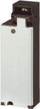
| AT0-02-...MT-ZBZ, magnet-powered interlock (open-circuit principle) | |
||||
| Interlocked | Released | Open | Door closed and interlocked | Energized:
rapid access possible in the event of mains failure or wire breakage. Both contacts closed |
|
|
To unlock door | Apply voltage to coil (A1, A2), e.g. via zero-speed monitor, enabling contact (21–22) opens | |||
| Door open | Only possible once it is released, door position contact (11–12) opens | ||||
| Door open | Both contacts blocked in the open position, even with tampering with simple tools | ||||
| Closing of door | Triple coding actuator cancels blocking of the enabling contact, door opening contact (11–12) closes | ||||
| To interlock door | Disconnect coil voltage:
1. Actuator interlocked 2. Enabling contact closed
|
||||
Switch must never be used as a mechanical stop! |
|||||