Eaton
|
|
 |
Series-C Frame Size - L Part Index CLICK HERE |
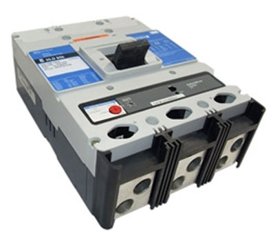
Type HLD (3-Pole) Shown |
|
HLD3250T52W — Electronic Circuit Breaker with Interchangeable Rating Plug
| Number of Poles |
Amperes | Interrupting Capacity |
Terminals |
|---|---|---|---|
| 3 | 250 | High 600 Vac Rated 65kAIC at 480 Vac Digitrip RMS 310+ LSI |
Standard |
Digitrip RMS 310 Trip Unit KEY:
L – Adjustable Long Delay Pickup (By Adjustable Rating Plug)
S – Adjustable Short Delay Pickup with Fixed Short Delay Time (I2t Response) or Adjustable Short Delay Time (Flat Response)
I – Adjustable Instantaneous Pickup by Setting Short Delay Time to Instantaneous
G – Adjustable Ground Fault Pickup with Adjustable Ground Fault Delay (Flat Response)
Quick Reference Guide
| UL 489 Interrupting Capacity Ratings(1) | |||||||
| Circuit Breaker Type |
Number of Poles |
Interrupting Capacity (kA rms Symmetrical Amperes) | |||||
|---|---|---|---|---|---|---|---|
| Volts AC (50/60 Hz) | Volts DC | ||||||
| 240 | 277 | 480 | 600 | 125 | 250(2)(3) | ||
| LDB | 2, 3 | 65 | — | 35 | 25 | — | 22 |
| LD | 2, 3, 4 | 65 | — | 35 | 25 | — | 22 |
| CLD(4) | 2, 3, 4 | 65 | — | 35 | 25 | — | — |
| HLD, HLDB | 2, 3, 4 | 100 | — | 65 | 35 | — | 25 |
| CHLD(4) | 2, 3, 4 | 100 | — | 65 | 35 | — | — |
| LDC, LDCB(5) | 2, 3, 4 | 200 | — | 100 | 50 | — | 30 |
| CLDC(4)(5) | 2, 3, 4 | 200 | — | 100 | 50 | — | — |
| IEC 947-2 Interrupting Capacity Ratings(1) | |||||||||
| Circuit Breaker Type |
Number of Poles |
Interrupting Capacity (kA Symmetrical Amperes) | |||||||
|---|---|---|---|---|---|---|---|---|---|
| Volts AC (50/60 Hz) | Volts DC | ||||||||
| 240 | 415 | 690 | 250(2)(3) | ||||||
| ICU | ICS | ICU | ICS | ICU | ICS | ICU | ICS | ||
| LDB | 2, 3 | 85 | 85 | 45 | 45 | 20 | 10 | 20 | 10 |
| LD | 2, 3, 4 | 85 | 85 | 45 | 45 | 20 | 10 | 20 | 10 |
| CLD(4) | 2, 3, 4 | 85 | 85 | 45 | 45 | 20 | 10 | — | — |
| HLD, HLDB | 2, 3, 4 | 100 | 100 | 70 | 70 | 25 | 13 | 20 | 10 |
| CHLD(4) | 2, 3, 4 | 100 | 100 | 70 | 70 | 25 | 13 | — | — |
| LDC, LDCB | 2, 3, 4 | 200 | 100 | 100 | 75 | 35 | 18 | 20 | 10 |
| CLDC(4) | 2, 3, 4 | 200 | 100 | 100 | 75 | 35 | 18 | — | — |
NOTES:
(1) Utilization Category A circuit breakers.
(2) L/R = 8 milliseconds minimum.
(3) Two-pole circuit breaker or two poles of three-pole circuit breaker. Incorporating thermal-magnetic trip unit only.
(4) 100% rated breakers.
(5) Current limiting.
Specifications
| Trip Unit Type |
Digitrip RMS 310 |
Digitrip OPTIM 550 |
Digitrip OPTIM 1050 |
|
|---|---|---|---|---|
| rms sensing | Yes | Yes | Yes | Yes |
| Breaker Type | ||||
| Frame | L | L | L | L |
| Ampere range | 300–600A | 300–600A | 200–600A | 200–600A |
| Interrupting rating at 480 volts |
35, 65, 100 (kA) | 35, 65, 100 (kA) | 35, 65, 100 (kA) | 35, 65, 100 (kA) |
| Protection | ||||
| Ordering options | LS, LSG | LSI, LSIG | LSI, LSI(A), LSIG | LSI(A), LSIG |
| Fixed rated plug (In) |
Yes | Yes | Yes | Yes |
| Overtemperature trip |
Yes | Yes | Yes | Yes |
| Long Delay Protection (L) | ||||
| Adjustable rating plug (In) |
Yes | Yes | No | No |
| Long delay pickup |
0.5–1.0 (In)(1) | 0.5–1.0 (In)(1) | 0.4–1.0 x (In) | 0.4–1.0 x (In) |
| Long delay time I2t |
12 seconds | 12 seconds | 2–24 seconds | 2–24 seconds |
| Long delay time I4t |
No | No | 1–5 seconds | 1–5 seconds |
| Long delay thermal memory |
Yes | Yes | Yes | Yes |
| High load alarm |
No | No | 0.5–1.0 x Ir | 0.5–1.0 x Ir |
| Short Delay Protection (S) | ||||
| Short delay pickup |
200–800% x (In) | 200–800% x (In) | 150–800% x (Ir) | 150–800% x (Ir) |
| Short delay time I2t |
100 ms | No | 100–500 ms | 100–500 ms |
| Short delay time flat |
No | Inst–300 ms | 100–500 ms | 100–500 ms |
| Short delay time zone selective interlocking |
No | No | Yes(4) | Yes |
| Instantaneous Protection (I | ||||
| Instantaneous pickup |
No | 200–800% x (In) | 200–800% x (In) | 200–800% x (In) |
| Discriminator | No | No | Yes | Yes |
| Instantaneous override |
Yes | Yes | Yes | Yes |
| Ground Fault Protection (G) | ||||
| Ground fault alarm |
No | No | 20–100% x (Is) | 20–100% x (Is) |
| Ground fault pickup |
1–5 x Ig (120A) | 1–5 x Ig (120A) | 20–100% x (Is) | 20–100% x (Is) |
| Ground fault delay I2t | No | No | 100–500 ms | 100–500 ms |
| Ground fault delay flat |
Inst–500 ms | Inst–500 ms | 100–500 ms | 100–500 ms |
| Ground fault zone selective interlocking |
No | No | Yes 4 | Yes |
| Ground fault thermal memory |
Yes | Yes | Yes | Yes |
| System Diagnostics | ||||
| Status LEDs | Yes | Yes | Yes | Yes |
| Cause of trip LEDs |
No | No | Yes | Yes |
| Magnitude of trip information |
No | No | Yes | Yes |
| Remote signal contact ground alarm |
Yes(5) | Yes(5) | Yes(4) | Yes |
| Local auxiliary and bell alarm contact |
Optional | Optional | Optional | Included |
| System Monitoring | ||||
| Digital display | No | No | Yes(1) | Yes(1) |
| Current | No | No | Yes | Yes |
| Power and energy |
No | No | No | Yes |
| Power quality harmonics |
No | No | No | Yes |
| Power factor | No | No | No | Yes |
| Communications | ||||
| PowerNet | No | No | Yes(2) | Yes |
| Testing | ||||
| Testing method | Test set | Test set | OPTIMizer, BIM, PowerNet | OPTIMizer, BIM, PowerNet |
Legend |
Notes: |
HLD3250T52W Dimensions
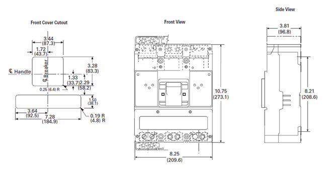 |
| Number of Poles | Width | Height | Depth |
|---|---|---|---|
| 2, 3 | 8.25 (209.6) | 10.75 (273.1) | 4.06 (103.1) |
| 4 | 11.00 (279.4) | 10.75 (273.1) | 4.06 (103.1) |